DeltaV SimulatePro adds capability to the DeltaV Simulate environment. Use DeltaV SimulatePro to coordinate the execution of modules executing in PlantWeb in a PC environment with process simulation packages. From the SimulatePro interface you can do several things:
- Enable and disable simulation
- Save and restore the state of the simulation at any time
- Set the execution rate of the simulation
- Play back operator changes at the specified execution rate
- Initialize dynamic blocks
- Pause and resume simulation
- View the modules and blocks in the simulation and change values if desired
- View converted external reference values and change them if desired.
SimulatePro includes a user interface from which these actions can be performed. These features can also be accessed by applications through OPC.
Be sure that Area_A is assigned to the ProfessionalPLUS workstation's Alarms and Events subsystem. If Area_A is not assigned, the current state of the simulation cannot be saved to a file.
DeltaV SimulatePro user interface
After you download the modules to a workstation, launch the SimulatePro interface from the Start menu by selecting .
If the SimulatePro interface is already running when you download, you must close and reopen it to update the information within SimulatePro.
The following figure shows the application opened to the Setup tab.
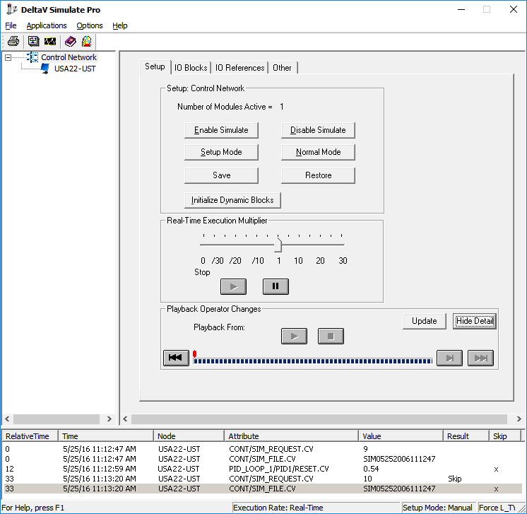
The tree view in the left pane of the application window contains a hierarchical view of the simulation nodes in the system. The tree view does not include controllers.
In the tree view you can select the entire Control System or individual nodes. The selection in the tree view determines the node or nodes affected by actions you take in the right pane.
The right pane contains the following tabbed dialogs: Setup, IO Blocks, IO References, and Other.
DeltaV SimulatePro menu functions
The following functions are found on the SimulatePro File menu:
-
Print – Use this command to print current
control simulation information. The
Print dialog allows the selection of a Summary
Report or a Detail Report.
- The Summary Report includes: a header containing a title and the time the print request was issued, as well as the simulation node name, the execution rate, the defined setup mode, whether or not the L_TYPE will be forced to Direct Independent on AI blocks and, a summary of the status of all modules in the simulation.
- The Detail Report prints the block details for the selected module and includes: a header containing a title and the time the print request was issued, as well as the name of the selected module and, a summary of the status of all blocks in the selected module.
- Exit – Use this command to exit the SimulatePro application.
- Clear History – Use this command to clear the items from the Playback View window and to delete change event records from the SimulatePro playback database.
The following functions are found on the DeltaV SimulatePro Applications menu:
The following functions are found on the DeltaV SimulatePro Options menu:
-
Setup – Use this command to define basic
process definitions required for SimulatePro to effectively manage control
simulation commands. Two pieces of information are defined on the
Options dialog:
- The setup mode, either MAN or AUTO.
- Whether or not the
L_TYPE of the AI blocks is to be forced to Direct Independent when
Enable Simulate is selected.
These options must be defined following the installation of SimulatePro. The current value for each option is shown on the status bar. If a function is selected that requires the Enable Simulation and Setup Mode information and the options have not yet been defined, the application prompts the user to define the information.
- Auto Save – Opens a dialog from which you can define settings to automatically save the state of the simulation at periodic intervals.
SimulatePro Setup tab
The SimulatePro Setup tab contains the following buttons and controls.
In the Setup: Control Network area:
- Enable Simulate – Sets the SIMULATE parameter to Enabled on all blocks with direct input reference in the currently selected node.
- Disable Simulate – Sets the SIMULATE parameter to Disabled on all blocks with direct input reference in the currently selected node.
- Setup Mode – Sets the target mode to the currently defined setup mode on all blocks with direct output reference in the currently selected node.
- Normal Mode – Sets the target mode on all blocks with direct output reference in the currently selected node to each block's configured normal mode.
-
Save – Saves the current state of the
simulation. You are prompted for a description. The file is stamped with the
date and time.
Note
Before restoring the simulation, download any changes made after saving.
- Restore – Restores the simulation state from a saved state. This button opens the Select Restore Time dialog from which you select a file for the time and date to restore.
- Initialize Dynamic Blocks – Resets all dynamic blocks (DI, DO, PIN, PID, Fuzzy, MPC, MPC-PRO, Rate Limit, Ratio, Splitter, Integrator, and Filter) in the currently selected node to their initial steady state conditions.
In the Real-Time Execution Multiplier area:
The modules' configured execution period and the Real-Time Execution Multiplier determine the execution rate of modules running in the workstation. Time-dependent function blocks use the actual configured execution period in their calculations. Thus, the behavior of the blocks is such that their calculations are done faster or slower than real time, depending on the Real-Time Execution Multiplier.
- Real-Time Execution Multiplier Slider Bar – Sets the execution rate for the simulation node. The execution multiplier may be set anywhere from 30 times slower than real-time to 30 times faster than real-time. An execution rate of 0 is defined as stopping execution. An execution rate of 1 is defined as real-time. Regardless of the execution rate, modules will not run faster than 100ms.
- Pause Execution – Saves the current execution rate of the simulation node and then sets the execution rate to stopped (0). The slider bar continues to show the saved rate but the execution rate status bar entry shows Paused. The Pause Execution button is disabled when the simulation is shown as Paused.
- Resume Execution – Sets the execution rate of the simulation node to the currently saved execution rate. The currently saved execution rate can be determined from the slider bar or by placing the cursor over the slider bar, which then displays the exact rate as a tooltip. The Resume Execution button is only enabled when the simulation is shown as Paused.
In the Playback Operator Changes area:
Operator changes can be played back after restoration from a saved file. The changes are played back at the rate specified by the Real-Time Execution Multiplier.
- Playback From – Shows the date and time at which the selected operator changes were saved.
- Update – Opens a dialog for selecting a time frame and refreshes details in the Playback View window with values saved in the SimulatePro playback database during the selected time frame.
- Show/Hide Detail – Shows or hides the playback details.
- Playback buttons – Start and cancel the playback, go to the next change event, and go to the previous and next save request points. Use the Pause and Resume Execution buttons in the Real-Time Execution Multiplier area for these functions.
- Progress bar – Shows the progress of the playback. The red markers on the progress bar show the save request points.
- Playback View window – Lists details about the change events to be played back. Context menu commands are available from change event records.
SimulatePro IO Blocks tab
The IO Blocks tab contains two grids: The Summary Module grid and the Summary Details grid.
The Summary Module grid shows simulation, status, and mode information for all of the modules in the currently connected simulation node.
-
Sim column – Contains a
 icon for modules that contain at least one relevant block that does not have
simulate enabled. This column applies only to input blocks such as AI and DI or
to control blocks with direct input I/O assigned.
icon for modules that contain at least one relevant block that does not have
simulate enabled. This column applies only to input blocks such as AI and DI or
to control blocks with direct input I/O assigned.
-
Status column – Contains a
icon for modules that contain at least one relevant block that has a bad or
uncertain simulate status. This column applies only to input blocks such as AI,
DI, or to control blocks with direct input I/O assigned.
-
Mode column – Contains a
icon for modules that contain at least one relevant block that is not in normal
mode. This column applies only to output blocks such as AO, DO or to control
blocks with direct output I/O assigned.
Click a column heading to sort the items in the column.
The Summary Details grid shows detailed information for blocks within a selected module. Choose a specific module by selecting that module in the Module Summary grid. For these details, the light gray background indicates fields that do not apply to that particular block's connection configuration. The red value indicates failure to go to the desired state for simulation.
- Sim column – Shows Enabled or Disabled. For input blocks and relevant control blocks, when the SIMULATE parameter is not set the word Disabled is displayed in red. For blocks that are not relevant, such as output blocks, this field has a light gray background.
- Value column – Shows the current value of the SIMULATE parameter for a block. For blocks that are not relevant, such as output blocks, this field has a light gray background.
- Status column – Shows the current Status of the SIMULATE parameter's value for a block. If the status of the value's status value is Bad or uncertain, the status appears in red on input and relevant control blocks. For blocks that are not relevant, such as output blocks, this field has a light gray background.
- Mode column – Shows two values separated by a forward slash for each block. The first value is the target Mode and the second value is the actual Mode for the block. For blocks that are not relevant, such as input blocks, this field has a light gray background.
- Out column – Shows the current OUT value for each block. For blocks that are not relevant, such as input blocks, this field has a light gray background.
Values in the Selected Module grid are changed by right-clicking the desired cell, and then selecting Edit from the context menu, or by double-clicking the desired value to change.
Click a column heading to sort the items in the column.
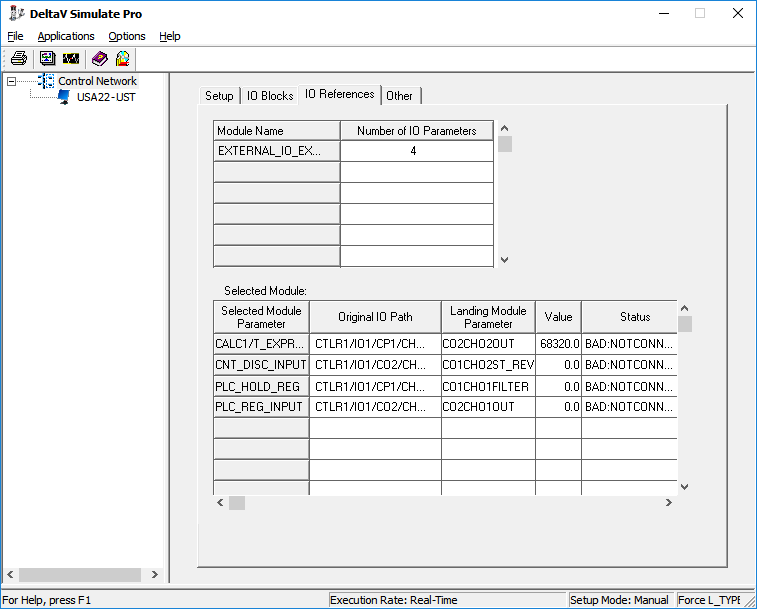
SimulatePro IO References tab
The IO References tab contains two grids: The Module grid and the Parameter Details grid. This tab is useful only if your configuration contains external references that have been converted using the Simulate Conversion utility.
The Module grid lists the modules that have external I/O references that have been converted. The number of parameters converted in each module is shown.
The Parameter Details grid shows the following information for each converted reference in the module selected in the summary grid:
The module parameters that are created for the converted references may be changed from this interface or through OPC.
SimulatePro Other tab
The Other tab contains the Other Module Summary grid.
The Other Module Summary grid lists the modules that do not have external I/O references that have been converted. Some control modules and most equipment and unit modules appear on the Other Module Summary grid.
All modules that do not appear on the IO Blocks tab or IO References tab are listed on the Other Module Summary grid.
Simulate Conversion utility
You must run the Simulate Conversion utility on the workstation before you run your simulation if your configuration contains:
The Simulate Conversion utility converts modules in the database so that fieldbus blocks and I/O references can be simulated for operator training and control system checkout. Function blocks that have been assigned to fieldbus devices are replaced with their equivalent DeltaV blocks. The block name, parameter values, and links to other blocks are preserved. If an equivalent block does not exist, as is the case for the FFMAI block, a composite block is substituted to support off-line simulation in Operator Interface and Control Studio. Parameters and function block expressions that perform I/O references are converted to external parameter references. When the Simulate Conversion utility is run, a module named M_nodename is automatically created under the workstation's Assigned Modules container. M_nodename is populated with parameters that are referenced by the converted modules' parameter and function block expressions' I/O references.
Modules can be downloaded to the workstation after conversion. Converted function blocks perform just like blocks assigned to fieldbus. For example, the logical and dynamic behavior of converted blocks is the same as assigned blocks. To simulate values that would normally be supplied through the I/O, the user or process simulation application can write to the newly created external parameter references that replaced the original I/O references.
To access the Simulate Conversion utility, right-click the workstation to which modules have been assigned in DeltaV Explorer, and then select Simulate Conversion.
After the Simulate Conversion utility runs, Control Studio can be used to view the changes made in the module. The assigned modules must be downloaded to view the converted module operation in Operator Interface, Control Studio, or SimulatePro.
The Simulate Conversion utility modifies the modules in the simulation system database. No utility is provided to reverse this conversion. The simulation system should be created from a copy of the actual system configuration.
The following sections provide more detail on the conversions.
Converting blocks assigned to fieldbus devices
Modules that contain function blocks such as AI, PID, AO that are assigned to a fieldbus device will not execute in DeltaV SimulatePro. The Simulate Conversion utility converts these blocks to the equivalent DeltaV function block so they will execute in SimulatePro. The following example shows the impact of a conversion on blocks assigned to fieldbus devices.

If a module contains fieldbus blocks for which no equivalent DeltaV block exists, the fieldbus blocks are replaced with composite blocks that support execution in a simulation environment. For example, the fieldbus function blocks FF_MAI, FFMDI, and FFMDO have no equivalent DeltaV blocks. Therefore, the Simulate Conversion utility substitutes the composite blocks MAI_SIM, MDI_SIM, and MDO_SIM for the fieldbus function blocks. Modules containing the substituted composite blocks cannot be accessed online using the SimulatePro interface. The composite blocks that support the conversion reside in the Simulation folder in the DeltaV Explorer Library/Composite Templates container. The simulation composite blocks are designed for use in a simulation environment only and are not meant for use in an online system.
The converted blocks contain SIMULATE_INx parameters that can be used to set the simulated OUTx parameters. The following images shows a module containing fieldbus blocks before and after conversion. Notice the SIMULATE_INx parameters after conversion and also notice that the block names and connections between parameters are not changed by the conversion.
After conversion, a process simulation tool can write to the SIMULATE_IN parameters and simulate the value and status that is normally provided by the I/O.
Converting parameters and expressions that reference I/O channels
Parameters and function block expressions such as a Calc/Logic block expression that directly references I/O channels will have Bad status when the associated module is assigned to a workstation. Also, the value and status cannot be written. The Simulate Conversion utility allows these parameters to be used for training and checkout. The conversion changes the I/O references to parameter references. A module called M_nodename that contains the reference parameters is automatically created on the workstation. Nodename is the name of the workstation on which the Simulate Conversion utility executed.
Note that the name of the module that is created by conversion is limited in length to 16 characters. Make sure that the node names in your configuration that will be converted will result in unique module names after truncation (if the workstation name is longer than 14 characters). Also, the references must refer to valid existing I/O parameters in the database before you run the Simulate Conversion utility.
For example, if a module assigned to the node NIGHTENGALE contains the parameter MYREF1, an I/O reference to CTLR2/IO1/CH05/OVERRANGE_PCT, after conversion this I/O reference parameter is changed to an external parameter reference. For this example, the path to the reference parameter is set to M_NIGHTENGALE/C02CH05OVERRAN1. The name of the parameter referenced in M_NIGHTENGALE is automatically created from the original I/O path definition (slashes are removed and the controller, card, channel, and parameter names are combined and shortened to 16 characters and given a unique name). After the I/O reference is converted, applications can read or write the converted external reference parameter to simulate the values and status normally provided by the I/O. The referenced parameters are automatically defined in the M_NIGHTENGALE module and can be accessed online using the SimulatePro interface.
The following example shows a module that contains parameter I/O references and expressions in a Calc/Logic block that also reference I/O.
The following image shows the impact on the blocks after the Simulate Conversion utility is run on the workstation that contains this module.
These converted I/O references can be accessed by examining the M_Nodename module or by selecting the IO Reference tab in the SimulatePro application as shown in the following figure.
Creating a training system
To create a training system from a configuration with fieldbus function blocks or parameters or function block expressions that reference I/O, you must run the Simulate Conversion utility once on every node. If new modules are added to the node, the Simulate Conversion utility can be re-run and any new parameters created to replace I/O references will automatically be added to the existing M_Nodename module.
The conversion modifies the configuration database on the workstation. SimulatePro does not include a utility to convert training system files back. The Simulate Conversion utility performs a one way transfer in which the actual system configuration is always the master configuration. The training system configuration can always be easily and quickly created from the actual configuration using the Simulate Conversion utility.
OPC interface development
You can use DeltaV Simulate to support the testing of an application program's OPC interface to the DeltaV system. Using this capability, you can verify the ability to read and write DeltaV parameters.
Full DeltaV OPC functionality is available in DeltaV Simulate. Executing modules in the computer allows an OPC interface to be checked out completely. You can use this feature to develop applications that will execute in the Application Station. The design of this OPC interface is illustrated in the following figure.