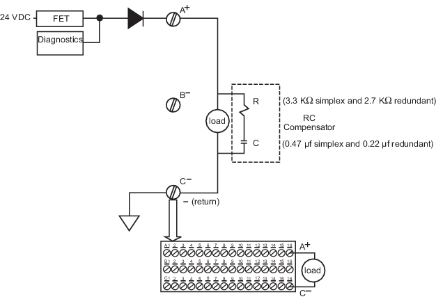
Installation notes
The R-C Compensator should not be used with LS DO CHARMs.
Pulse testing is recommended; however, it can be disabled for field devices such as solid state relays or active electronics that cannot support it. With redundant Logic Solvers, pulse testing requires partner synchronization and stops if the redundant partner becomes unavailable.
Line fault detection is not compatible with significant capacitive loading (cable + load > 30 nF) and must be disabled under these conditions.
Specifications
|
Item |
Specification |
|---|---|
|
Each channel is optically isolated from the system and factory tested to 1500 VDC. No channel-to-channel isolation. |
|
|
Open loop test off: 4.5 µA typical; 10 µA max. Note Optional pulse test will apply 24 VDC pulse on line for 1.0 mS every 50 mS. Refer to the Installation notes for more information on pulse testing. |
|
|
< 5 Ω for > 1 second with +24 VDC field power. Refer to the Installation notes for information on pulse testing. |
|
|
Line fault detection - open circuit (with +24 VDC field power) |
Refer to the Installation notes for information on pulse testing. |