The Auxiliary Relay DTA-Inverting module energizes the field when Discrete Out is turned Off.
The Auxiliary Relay DTA-Inverting module is paired with the Auxiliary Relay Diode module to perform the required function such as monitoring field wiring when not actuated. A switch on the Auxiliary Relay Diode module is used to change between Energize to Actuate and De-Energize to Actuate. The Auxiliary Relay DTA-Inverting module's LED shows if power is correctly installed and the state of the relay coil.
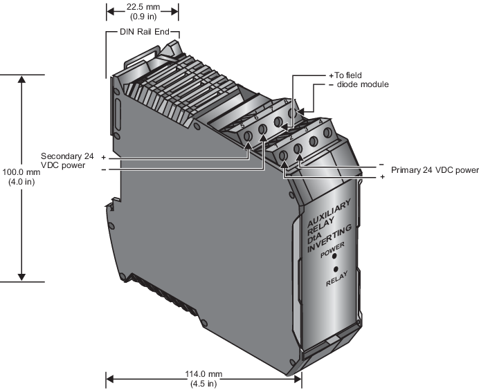
The Auxiliary Relay DTA-Inverting module has the following connections:
- Two pin connections for primary power
- Two pin connections for secondary power
- Two pin connections for field output to the Auxiliary Relay Diode module
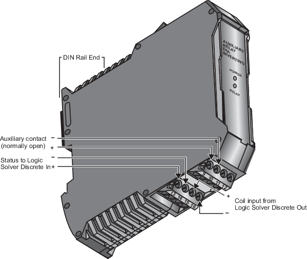
- Two pin connections for coil input
- Two pin connections for status output
- Two pin connections for auxiliary output contact closure (not used in the application depicted in the following figure).
The line fault detection values in the following table only apply when line fault detection is enabled. When line fault detection is not enabled, the On states detect opens only and the Off states detect shorts only.