Installation notes
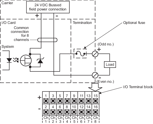
- The Fused 8-channel terminal block is recommended to provide terminations for field wiring for the DO 8-channel 24 VDC high-side card. Optional terminal blocks are the 8-channel terminal block and the 16-pin mass terminal block. If you use a mass terminal block with the DO 8-channel 24 VDC high-side I/O card, refer to the terminal block specifications for the output rating for each block. Those specifications might be more restrictive than the specifications listed in the following table.
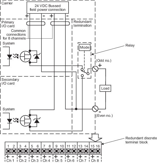
- The Redundant Discrete 8-channel terminal block is recommended to provide terminations for field wiring for the redundant DO 8-channel 24 VDC high-side card.
- The DO 8-channel 24 VDC high-side card has line fault detection that can be enabled on a channel-by-channel basis as a configuration item. When line fault detection is enabled, the card detects open and short line fault conditions by performing an internal readback of the output to verify its value in both on and off states. The card tests the opposite state of its current value by temporarily changing the output to that value, performing the internal readback, then returning the output to its configured output value. The pulses to the opposite state are never greater than 200 microseconds. High speed inputs that connect to a DO channel with line fault enabled must consider these pulses in the input software scheme. When line fault detection is not enabled, a more limited detection of open and short line fault conditions is available on the active redundant card only. This is accomplished by the internal readback mechanism without pulsing the output to the opposite state. Therefore, shorts can be detected only when the DO channel is on, and opens can be detected only when the DO channel is off. When line fault detection is not enabled, and the card is simplex, line fault tests do not run and line fault conditions are not reported.
- When pulse testing is enabled, the LED on the output device may be slightly illuminated.
- This card requires an S-series controller.
Note
Line fault detection is not compatible with significant capacitive loading (cable + load > 30 nF) and must be disabled under these conditions.