Installation notes
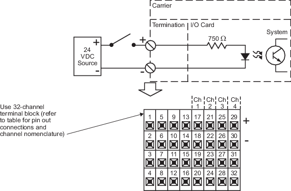
- The Discrete 32-channel terminal block is recommended to provide terminations for field wiring for the Pulse count input card. The table Table: Discrete 32-channel terminal block used with the Pulse count input card lists the pin out connections for the Pulse count input card.
- The Pulse count input card's discrete input channel has a switching hysteresis of 80 mV. Noise signals above this amplitude are detected by the input channel.
- This card requires an S-series controller.
Specifications
| Item | Specification |
|---|---|
| Number of channels | Four |
| Detection level for ON | 4.8 VDC (minimum) |
| Detection level for OFF | 1.0 VDC (maximum) |
| Input impedance | 3 to 25 mA at 5 to 24 VDC |
| Input accuracy | 0.1% reading (over 10 Hz - 50 kHz signals)(1) |
| Input frequency | |
| Resolution | 1 pulse |
| Minimum pulse width | 10 microseconds |
| Maximum input voltage | 26.4 VDC |
| Resolution counter | 32 bits |
| LocalBus current | 150 mA maximum |
| Heat dissipation | 5.3 W |
| Isolation | Each channel is optically isolated from the system and from each other and factory tested to 1500 VDC. |
| Mounting | Assigned slot of I/O carrier |
(1) Filtering may be required to meet the accuracy specification for a
pulse input channel.
Terminal block connections
| Terminal | Channel nomenclature | Terminal | Channel nomenclature |
|---|---|---|---|
| Terminal 1 | Reserved for future use | Terminal 17 | DI or PIN (pulse input), Ch1+ |
| Terminal 2 | Reserved for future use | Terminal 18 | DI or PIN (pulse input), Ch1- |
| Terminal 3 | Reserved for future use | Terminal 19 | Reserved for future use |
| Terminal 4 | Reserved for future use | Terminal 20 | Reserved for future use |
| Terminal 5 | Reserved for future use | Terminal 21 | DI or PIN (pulse input), Ch2+ |
| Terminal 6 | Reserved for future use | Terminal 22 | DI or PIN (pulse input), Ch2- |
| Terminal 7 | Reserved for future use | Terminal 23 | Reserved for future use |
| Terminal 8 | Reserved for future use | Terminal 24 | Reserved for future use |
| Terminal 9 | Reserved for future use | Terminal 25 | DI or PIN (pulse input), Ch3+ |
| Terminal 10 | Reserved for future use | Terminal 26 | DI or PIN (pulse input), Ch3- |
| Terminal 11 | +24 VDC | Terminal 27 | Reserved for future use |
| Terminal 12 | - 24 VDC (return) | Terminal 28 | Reserved for future use |
| Terminal 13 | Reserved for future use | Terminal 29 | DI or PIN (pulse input), Ch4+ |
| Terminal 14 | Reserved for future use | Terminal 30 | DI or PIN (pulse input), Ch4- |
| Terminal 15 | +24 VDC | Terminal 31 | Reserved for future use |
| Terminal 16 | - 24 VDC (return) | Terminal 32 | Reserved for future use |