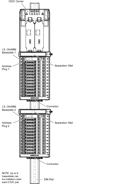
Up to eight I.S. baseplates can be installed under a CHARM I/O Carrier on a DIN rail. The I.S. baseplates and CHARM I/O Carrier connect together to form a redundant power and communication bus.
I.S. CHARM Baseplates can also be installed under the same CIOC as standard (non I.S.) CHARM Baseplates. When I.S. CHARM Baseplates and standard CHARM Baseplates are installed under the same CIOC Carrier, standard baseplates must be installed between the CIOC Carrier and the I.S. CHARM Baseplate. A Separation Wall must be installed on every I.S. baseplate and every component, such as extenders and terminators after the I.S. baseplates. The following figure shows a standard baseplate (non-I.S.) installed between the CIOC Carrier and I.S. baseplates.
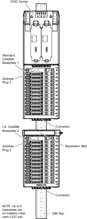
Refer to Figure: Installing I.S. Baseplates