Before extending bussed field power to VerticalPLUS carriers, read the note and warning in "Extending Bussed Field Power".
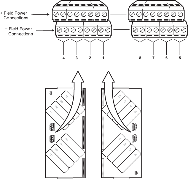
Bussed field power can be extended to VerticalPLUS carriers if the addition of the next I/O card does not exceed the 13 A rating of the connection to the source. The following figure shows the screw terminal assignments on the VerticalPLUS carriers’ bussed field power connections.
 WARNING!
For VerticalPLUS carriers, field power for one I/O card can be extended to additional I/O cards only if they have the same field voltage requirements.
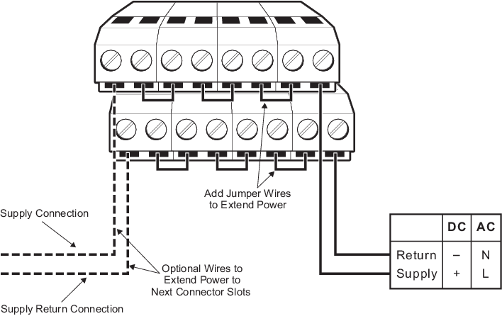
If the bussed field power supplies one I/O card only and is not extended to additional I/O cards such as in redundant card applications, connect the wiring to the assigned screw terminal connections on the I/O interface carrier as shown in Figure: Bussed Field Power Wiring for One Power Supply Per I/O Card on VerticalPLUS Carriers.
CAUTION!Ensure that the factory installed jumpers are removed from the connectors if only one I/O card is to be powered.
 WARNING!
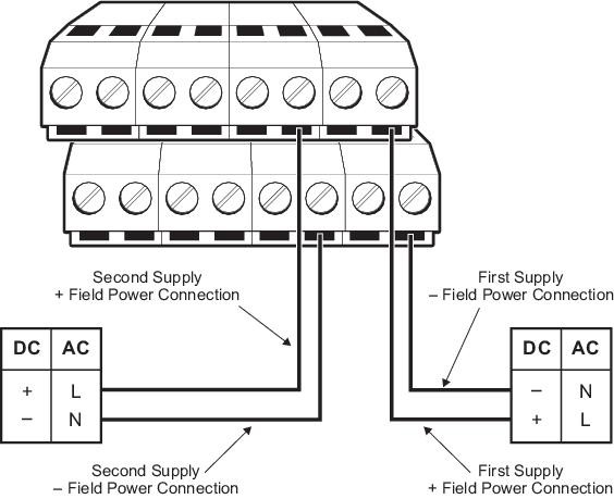
When supplying 250 VAC to adjacent bussed field power connections, be sure both sources are the same phase.
If the bussed field power is extended to two I/O cards, connect the wiring to the assigned screw terminal connections on the I/O interface carrier as shown in the following figure. Be sure that jumpers are installed as shown in the figure.
 WARNING!
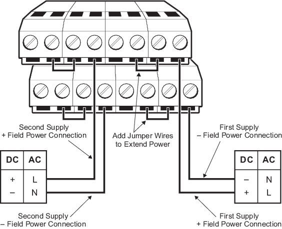
When supplying 250 VAC to adjacent bussed field power connections, be sure both sources are the same phase.
If the bussed field power is extended to four I/O cards, connect wiring to the assigned screw terminal connections on the I/O interface carrier as shown in the following figure. Be sure that jumpers are installed as shown in the figure.