The decision to extend bussed field power depends on plant standards and procedures. However, if separate power supplies, breakers, or shutdown switches are required, it is not recommended that bussed field power be extended.
For all carrier types, supply the same voltage at bussed field power to all cards on a carrier whenever possible. Supply clean bussed field power to the I/O carriers and use inductive noise reduction techniques on I/O signals. Refer to Appendix K for bussed field power guidelines.
 WARNING!
If more than one bussed power source is used, place a label near the bussed field power connectors containing the following English and French statements: “WARNING: MORE THAN ONE LIVE CIRCUIT. SEE INSTALLATION DIAGRAM.” “AVERTISSEMENT: CÉT EQUIPMENT RENFERME PLUSIEURS CICUITS SOUS TENSION. VOIR LE SCHÉMA D’INSTALLATION”.
Extending Bussed Field Power to Horizontal and Legacy Vertical Carriers
This section explains how to extend bussed field power to the horizontal and Legacy Vertical carriers. For VerticalPLUS carriers, refer to the “Extending Bussed Field Power to VerticalPLUS Carriers” topic.
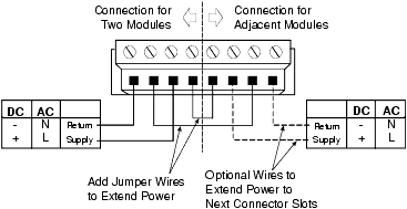
Bussed field power can be extended to horizontal carriers and Legacy Vertical carriers if the addition of the next two I/O cards does not exceed the 6.5 A rating of the connection to the source. Figure: Bussed Field Power Connector on Horizontal and Legacy Vertical Carriers shows the screw terminal assignments on the bussed field power connector on horizontal and Legacy Vertical carriers.
WARNING!For Legacy Vertical and horizontal carriers, field power for one I/O card can be extended to additional pairs of I/O cards only if they have the same field voltage requirements.
WARNING!If extending bussed field power to Legacy Vertical and horizontal carriers, removing the connector will remove power from all extended connectors.
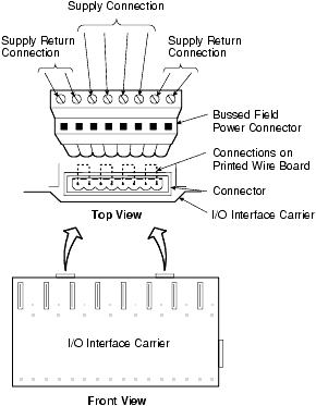
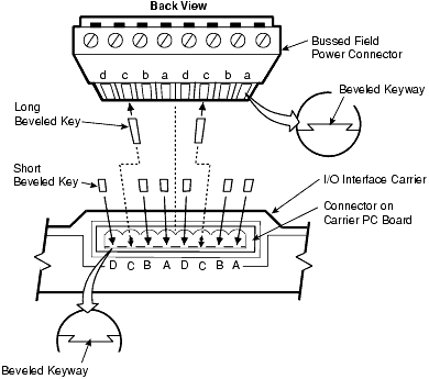
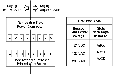
This connector can be used for both DC and AC power.
Wire the bulk power supply for bussed field power
The following information pertains to horizontal and Legacy Vertical Carriers. For VerticalPLUS carriers refer to Appendix M.
- If the bussed field power
supplies one pair of I/O cards only and is not extended to additional I/O
cards, connect wiring to the assigned screw terminal connection on the top of
the I/O interface carrier as shown in
Figure: Bussed Field Power Wiring Diagram.
Note
You might prefer to remove the screw terminal connector to install wiring and replace it on the I/O interface carrier after wiring is installed.
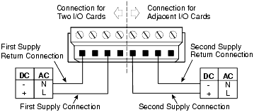
- If the bussed field power is extended to additional I/O cards, connect wiring to the assigned screw terminal connection on the top of the I/O interface carrier as shown in Figure: Bussed Field Power Wiring Diagram (Extended Power).
 WARNING!
When power is extended, removing the connector will break the connection between the power supply and downstream devices.
Refer to Appendix J for power supply overviews.