-
Make and test the required Control Network cables. See the
section, "Control Network Specifications" for cable guidelines and
specifications. Select the appropriate cable type on the cable test tool and
follow the detailed instructions in the test tool’s manual.
You must connect the test equipment to both ends of the cable to test it properly. The testing tool checks each cable based on its type and issues a Pass or Fail reading. Make sure the cable passes each test. The tests supported by the Microtest PentaScanner testing tool include the following:
- Cable mapping
- Length
- Crosstalk
- Attenuation
- Attenuation-to-crosstalk ratio
- Impedance
- Loop resistance
- Capacitance
 CAUTION!
Substandard cables can create serious communication problems. Make sure all cables meet the specifications listed in the "Control Network Specifications" section.
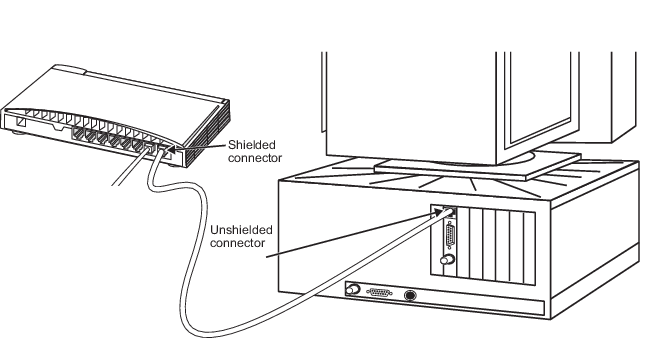
- If you have a simplex Control Network, connect the unshielded end of a network cable to the twisted pair port on the primary Network Interface Card (NIC) and connect the shielded end of the cable to the primary switch as shown in the following figure.
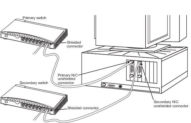
- If you have a redundant Control Network, connect the unshielded end of a network cable to the twisted pair port on the workstation’s primary NIC and connect the shielded end of the cable to the primary switch as shown in Figure: Redundant Control Network Cable Connections. Connect another cable from the twisted pair port on the workstation’s secondary NIC to the secondary switch. It is helpful to identify the Control Network cables with color-coded boots. Emerson recommends the following conventions: a yellow color-coded boot for the primary Control Network cable and a black color-coded boot for the secondary Control Network cable.
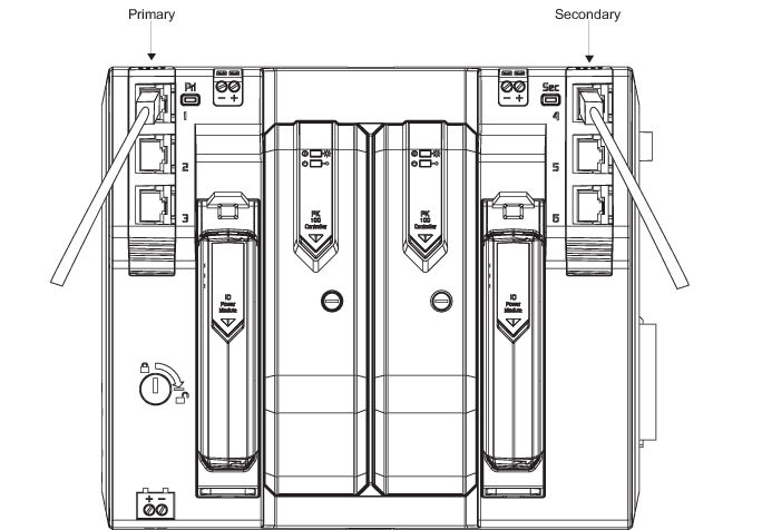
- Connect network cables from the switches to the RJ45 connectors on the front of the carrier. The left side ports are the primary ports and the right side are the secondary ports (for use with redundant networks). The ports must be enabled on the controller's Properties page in DeltaV Explorer.