The DeltaV software includes the PID_AT module template. The template is for a simple PID loop that includes analog tracking.
This module template is set up for input and output Device Signal Tags. You can add additional blocks if necessary, for example when the controlled variable is characterized or selected. Configure analog tracking conditions on the AT block. The module template includes configuration tips when viewed in Control Studio.
Use the AT_VLV_ dynamo to monitor and control loops that use this module template. The dynamo opens the LOOP_FP faceplate. From the faceplate you can open the LOOP_DT detail display for the module and the module's Analog Tracking block faceplate.
Implementation example
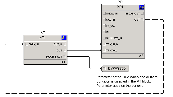
This example uses the Analog Tracking function block to generate a tracking flag and a tracking value that connects to a PID function block. The output OUT_D of the Analog Tracking function block represents the tracking flag and it is wired directly to the input TRK_IN_D of the PID function block. The OUT parameter of the Analog Tracking function block represents the tracking value and is wired directly to the input TRK_VAL of the PID function block.
-
The Initial condition is that all tracking conditions evaluate to False (OUT_D of the AT block is False).
-
Then tracking Condition 2 evaluates to True, T_OUT_D2 = True (and T_RESET_REQD2 = False), OUT_D becomes True.
-
If T_VAL2 = 10, the analog output OUT = 10.
-
Now, tracking Condition 3 evaluates True, T_OUT_D3 = True (and T_RESET_REQD3 = False), OUT_D stays True.
-
If T_VAL3 = 20, the analog output OUT remains 10 because the T_VALn associated with the first active condition in the order of tracking conditions is Condition 2.
-
Now, Condition 2 evaluates to False: T_OUT_D2 = False.
-
OUT_D remains True because T_OUT_D3 is still True.
-
But OUT = 20 because the first active condition in the order of tracking conditions is Condition 3.