The DCC block evaluates up to 16 interlock conditions, 8 permissive conditions, and 8 force setpoints. The output of an interlock or permissive condition can be delayed on, delayed off, or disabled. The output of a force setpoint can be delayed on or disabled.
The block can optionally latch one or more active interlock conditions to keep the interlock discrete output False until no interlock conditions are active and a reset is triggered.
This block generates outputs that can be used by an Enhanced Device Control (EDC) function block as inputs for interlock, permissive, and force setpoint functionality. The block has the ability to save the first interlock condition as well. The block can be used with the DC block but support is limited: The DC block does not support force setpoints and does not have a parameter to wire to the interlock state.
- I_OUT_D — the interlock discrete output used as the interlock input of an EDC or DC block.
- I_OUT — the state to which to interlock an EDC block. You cannot wire I_OUT to a DC block.
- I_OUT_INT — the weighted binary sum of the interlock conditions.
- I_FIRST_OUT — the bit value of the highest priority condition (lowest condition number) that is currently active. If another condition that has a different interlock state (I_STATEn) and a higher priority becomes active, I_FIRST_OUT changes to the bit value of the newly active condition
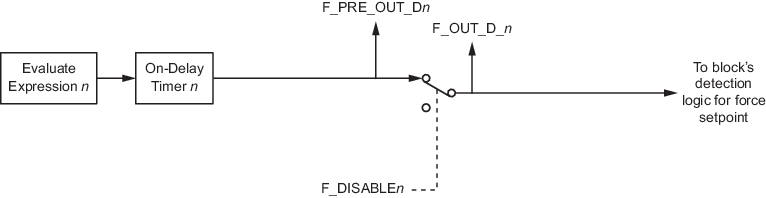
For forced setpoints, the DCC block generates three outputs:
An event chronicle entry is added when the first detection of an interlock condition evaluates true or when any interlock condition becomes true that changes the interlock state output or when all active interlock conditions have cleared. The event contains at a minimum the number and description and the interlock state value of the condition(s).
The block supports signal status propagation and generates a bypass alarm when at least one of the interlock, permissive, or force setpoint input conditions is disabled.
The DCC block does not support modes.
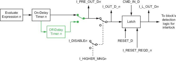
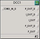
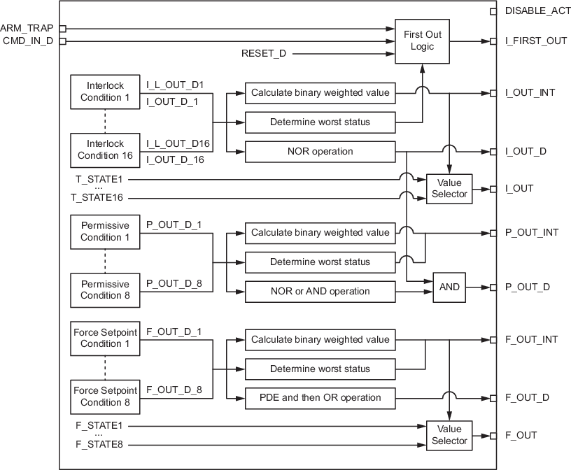
The following diagram shows the internal components of the Discrete Control Condition function block.
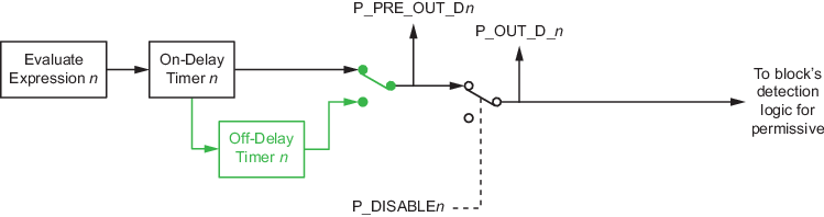
The following figures show the details of the conditions of the Discrete Control Condition function block.